

How Many Bytes Are In The Bx Register?
Chapter � 3 Addressing Modes
�
����������������������������������������������������������������������������������������������������
Introduction
�������� Efficient software evolution for the microprocessor requires a complete familiarity with the addressing modes employed by each instruction. These are
1. Information addressing modes,
2. Memory addressing modes, and
3. Stack addressing.
The data-addressing modes include ;
i. register,
ii. immediate,
3. straight,
4. register indirect,
five. base of operations �plus-index,
6. register relative, and
7. base of operations relative-plus-alphabetize
in the 8086 through the 80286 mi�croprocessor. The 80386 and above too
8. include scaled-index
mode of addressing memory data.
The plan memory-addressing modes include
1. program relative,
2. direct, and
iii. indirect.
The functioning of the stack retentivity is explained then that the Push button and POP instructions are understood.
three. Data-Addressing Modes
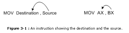
�������� Considering the MOV teaching is a mutual and flexible instruction, it provides a basis for the ex�planation of the data-addressing modes. Figure 3-1 illustrates the MOV instruction and defines the management of data flow. The source is to the correct and the destination is to the left, next to the op�code MOV. An opcode, or performance lawmaking, tells the microprocessor which performance to perform.
dIn Figure 3-1, the MOV AX,BX instruction transfers the word contents of the source reg�ister (BX) into the destination register (AX). The source never changes, just the destination usu�ally changes.ane It is essential to recall that a MOV instruction always copies the source data and into the destination. The MOV never actually picks upward the data and moves it. Also, note that the flag annals remains unaffected by nigh data transfer instructions. The source and destina�tion are ofttimes chosen operands.
The data-addressing modes are as follows:
three.i. Register Addressing
�������� Annals addressing is the nearly common form of data addressing. The microprocessor contains the following 8-bit registers used with register addressing: AH, AL, BH, BL, CH, CL, DH, and DL. Also present are the fol�lowing 16-bit registers: AX, BX, CX, DX, SP, BP, SI, and DI. In the 80386 and above, the ex�tended 32-bit registers are EAX, EBX, ECX, EDX, ESP, EBP, EDI, and ESI. With register addressing, some MOV instructions, and the PUSH and POP instructions, also use the 16-scrap segment registers (CS, ES, DS, SS, FS, and GS).
It is important for instructions to use registers that are the same size. Never mix an eight-bit annals with a 16-chip register, an 8-flake register with a 32-bit annals, or a xvi-bit register with 32-bit register considering this is not immune by the micro�processor and results in an mistake when assembled. This is fifty-fifty truthful when a MOV AX,AL or a MOV EAX,AL teaching may seem to brand sense. Of course, the MOV AX,AL or MOV EAX,AL teaching is not allowed considering these registers are of different sizes. Annotation that a few instructions, such every bit SHL DX,CL, are exceptions to this rule. It is as well important to note that none of the MOV instructions affect the flag bits.
Table 3-1 shows some variations of register motility instructions. It is impossible to show all combinations considering there are as well many. A segment-to-segment annals MOV instruction is non allowed. Notation that the code segment register is not unremarkably changed by a MOV instruction because the address of the side by side instruction is constitute in both IP/EIP and CS. If just CS were changed, the address of the side by side didactics would exist un�predictable. Therefore, changing the CS annals with a MOV instruction is not allowed.
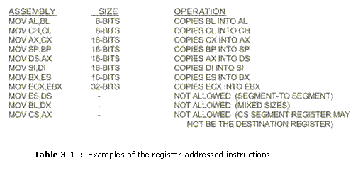
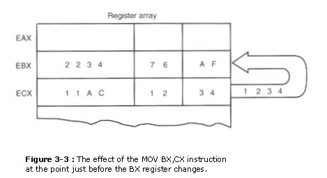
Figure 3-3 shows the operation of the MOV BX,CX teaching. Note that the source regis�ter�s contents do not change, but the destination annals�south contents do change. The instruction copies a 1234H from register CX into register BX. This erases the old contents (76AFH) of register BX, but the contents of CX remain unchanged. The contents of the destination annals or destination memory location change for all instructions except the CMP and Examination instructions. Annotation that the MOV BX, CX educational activity does not bear upon the leftmost 16 bits of annals EBX.
three.ii. Immediate Addressing
������ Another data-addressing style is immediate addressing. The term immediate implies that the data immediately follow the hexadecimal opcode in the retentiveness. Likewise note that immediate data are con�stant data, while the data transferred from a annals are variable data. Immediate addressing oper�ates upon a byte or word of information. In the 80386 through the Pentium II microprocessor, firsthand addressing besides operates on doubleword data. The MOV firsthand instruction transfers a copy of the immediate information into a annals or a memory location. Figure 3-4 shows the operation of a MOV EAX,13456H instruction. This instruction copies the 13456H from the didactics, located in the retentiveness immediately following the hexadecimal opcode, into register EAX. Equally with the MOV teaching illustrated in Figure 3-3, the source data overwrites the destination information.
The symbolic assembler portrays immediate data in many means. The letter H appends hexa�decimal data. If hexadecimal data brainstorm with a letter of the alphabet, the assembler requires that the data beginning with a 0. For example, to represent a hexadecimal F2, a 0F2H is used in assembly language. An ASCII-coded character or characters may be depicted in the immediate form if the ASCII data are enclosed in apostrophes. (An example is the MOV BH,�A� instruction, which moves an ASCII-coded A (41H) into register BH.) Be careful to use the apostrophe (�) for ASCII data and not the single quotation marking . Bi�nary information are represented if the binary number is followed by the letter B, or, in some assemblers, the letter Y. Table 3-2 shows many different variations of MOV instructions that utilize immediate data.

Direct Data Addressing
�������� Most instructions can apply the direct information-addressing fashion. In fact, directly information addressing is ap�plied to many instructions in a typical program. There are two bones forms of direct information ad�dressing:
i.Direct addressing, which applies to a MOV between a memory location and AL, AX, or EAX, and
two.Displacement addressing, which applies to well-nigh whatever instruction in the education set. In either instance, the accost is formed by calculation the displacement to the default data segment address or an alternate segment address.
Straight Addressing; Direct addressing with a MOV instruction transfers data between a retentivity location, located within the data segment, and the AL (8-bit), AX (16-bit), or EAX (32-bit) reg�ister. A MOV didactics using this blazon of addressing is unremarkably a 3-byte long instruction. (In the 80386 and above, a annals size prefix may appear before the instruction, causing information technology to exceed three bytes in length.)
The MOV AL,Data instruction, as represented by near assemblers, loads AL from data segment retentiveness location DATA (1234H). Memory location DATA is a symbolic retention lo�cation, while the 1234H is the bodily hexadecimal location. With many assemblers, this instruc�tion is represented as a MOV AL,[1234H17 instruction. The [1234H] is an absolute memory location that is not immune by all assembler programs. Notation that this may need to be formed as MOV AL,DS:[l234Hj with some assemblers, to prove that the address is in the data segment. Figure 3�5 shows how this education transfers a copy of the byte-sized contents of memory lo�cation eleven 234H into AL. The effective address is formed by calculation I 234H (the offset address) to 1000H (the data segment address of I000H) in a system operating in the real mode.
Table 3�3 lists the three straight addressed instructions. These instructions often appear in programs, so Intel decided to make them special three-byte long instructions to reduce the length
of programs. All other instructions that move data from a memory location to a register, called displacement-addressed instructions, require iv or more bytes of memory for storage in a program.
Displacement Addressing. Displacement addressing is almost identical to direct addressing, except that the teaching is 4 bytes broad instead of three. In the 80386 through the Pentium Two, this education tin be upward to seven bytes wide if a 32-bit register and a 32-fleck displacement are spec�ified. This blazon of direct information addressing is much more flexible because most instructions use it.
If the operation of the MOV CL,DS:[l234H] instruction is compared to that of the MOV AL,DS: [I 234Hj instruction of Figure 3�5, both basically perform the same operation except for the destination register (CL versus AL). Another difference only becomes apparent upon test�ining the assembled versions of these two instructions. The MQV AL,DS:[1234H] instruction is three bytes long and the MOV CL,DS: [12341-I] instruction is 4 bytes long, equally illustrated in Ex�aplenty 3�4. This instance shows how the assembler converts these two instructions into hexa�decimal machine linguistic communication. You must include the segment register DS: in this example, before the [outset] function of the instruction. You may use any segment register, but, in nigh cases, data are stored in the information segment, so this example uses DS:[1234H].
Table 3�iv lists some MOV instructions, using the displacement form of direct addressing. Not all variations are listed because there are many MOV instructions of this type. The segment registers can exist stored or loaded from memory.
Example 3�5 shows a short program using models that address information in the information seg�ment. Note that the information segment begins with a Data argument to inform the assembler where the data segment begins. The model size is adjusted from TINY, equally shown in Example iii�3, to SMALL so that a data segment can be included. The Pocket-size model allows one data segment and ane code segment. The SMALL model is often used whenever memory data are required for a programme. A SMALL model program assembles as an execute (.EXE) program. Notice how this instance allocates retentiveness locations in the data segment by using the DB and DW directives. Here the .STARTUP argument not only indicates the start of the code, but it also loads the data segment register with the segment address of the data segment. If this program is assembled and
executed with CodeView, the instructions can be viewed as they execute and change registers and memory locations.
Annals Indirect Addressing
Register indirect addressing allows information to be addressed at any memory location through an offset address held in any of the following registers: BP, BX, DI, and SI. For example, if register BX contains a l000H and the MOV AX,[BX] instruction executes, the discussion contents of data segment offset accost I 000H are copied into annals AX. If the microprocessor is operated in the real mode and DS = OIOOH, this instruction addresses a give-and-take stored at memory bytes 2000H and 2001H, and transfers it into register AX (see Figure 3�6). Note that the contents of 2000H are moved into AL and the contents of 2001H are moved into AH. The [ ] symbols announce indirect addressing in associates language. In addition to using the BP, BX, DI, and SI registers to indirectly accost memory, the 80386 and above allow register indirect addressing with whatever extended register ex�cept ESP. Some typical instructions using indirect addressing announced in Table 3�5.
The data segment is used by default with annals indirect addressing or any other ad�dressing style that uses BX, DI, or SI to accost retention. If the BP annals addresses retention, the stack segment is used by default. These settings are considered the default for these four index and base registers. For the 80386 and higher up, EBP addresses retentivity in the stack segment by default; FAX, EBX, ECX, EDX, EDT, and ESI accost retentiveness in the data segment by de�fault. When using a 32-bit register to address memory in the real mode, the contents of the 32-bit register must never exceed 0000FFFFH. In the protected mode, whatsoever value can be used in a 32-chip register that is used to indirectly address memory, equally long as it does not admission a location outside of the segment, equally dictated by the access rights byte. An example 80386/80486/Pentium II in�struction is MOV EAX,[EBX]. This instruction loads FAX with the doubleword-sized number stored at the data segment offset address indexed by EBX.
In some cases, indirect addressing requires specifying the size of the information are specified with the special assembler directive BYTE PTR, Discussion PTR, or DWORD PTR. These directives point the size of the memory data addressed past the memory pointer (PTR). For instance, the MOV AL ,[DIJ instruction is clearly a byte-sized movement instruction, but the MOV [DI], 1OH instruction is ambiguous. Does the MOV [DIJ,10H instruction accost a byte-, word-, or double-word-sized retention location? The assembler can�t determine the size of the IOH. The education MOV BYTE PTR [DI],IOH conspicuously designates the location addressed by Dl as a byte-sized retentiveness location. Likewise, the MOV DWORD PTR [DI],IOH conspicuously identifies t~ie retention lo�cation as doubleword-sized. The BYTE PTR, WORD PTR, and DWORD PTR directives are used only with instructions that address a retentivity location through a pointer or index register with immediate data, and for a few other instructions that are described in subsequent chapters.
Indirect addressing often allows a pi cam to refer to tabular information located in the retentiveness system. For example, suppose that y'all must create a tabular array of information that contains 50 samples taken from memory location 0000:046C. Location 0000:046C contains a counter that is main�tained by the personal computer�s existent-fourth dimension clock. Figure 3�7 shows the table and the BX annals used to sequentially address each location in the table. To accomplish this task, load the starting location of the table into the BX register with a MOV firsthand educational activity. Afterward initializing the starting address of the table, use register indirect addressing to shop the 50 samples sequentially.
The sequence shown in Case iii�6 loads register BX with the starting address of the table and initializes the count, located in register CX, to fifty. The OFFSET directive tells the as�sembler to load BX with the offset address of memory location TABLE, not the contents of
Tabular array. For example. the MOV BX,DATAS education copies the contents of memory location DATAS into BX, while the MOV BX,OFFSET DATAS didactics copies the offset address of DATAS into BX. When the Starting time directive is used with the MOV instruction, the assembler calculates the offset accost and and so uses a MOV immediate instruction to load the accost into the specified 16-scrap register.
In one case the counter and arrow are initialized, a repeat-until CX = 0 loop executes. Here, data are read from extra segment memory location 46CH with the MOV AX,ES:[046CH] in�struction and stored in memory that is indirectly addressed by the starting time address located in reg�ister BX. Adjacent, BX is incremented (one is added to BX) to the side by side table location, and finally the LOOP instruction repeats the LOOP 50 times. The LOOP education decrements (subtracts one from) the counter (CX); if CX is not null, LOOP causes a jump to memory location Once again. If CX becomes zero, no jump occurs and this sequence of instructions ends. This case copies the most recent fifty values from the clock into the memory array DATAS. This program will oft show the same data in each location considering the contents of the clock are inverse simplyiv 18.two times per 2nd. To view the program and its execution, use the CodeView plan. To
use CodeView, blazon CV FILE.EXE or access it as DEBUG from the Programmer�s WorkBench program under the RUN carte du jour. Note that CodeView functions only with .EXE or .COM files. Some useful CodeView switches are /l for a fifty-line display and IS for use of high-resolution video displays in an application. To debug the file Test.COM with l lines, blazon CV /50 Examination.COM at the DOS prompt.
Base-Plus-Alphabetize Addressing
Base-plus-index addressing is similar to indirect addressing considering it indirectly addresses memory data. In the 8086 through the 80286, this type of addressing uses 1 base annals (BP or BX), and one alphabetize register (DI or SI) to indirectly address retentiveness. The base register often holds the outset location of a memory array, while the index register holds the relative posi�tion of an element in the array. Remember that whenever BP addresses memory data, both the stack segment register and BP generate the effective address.
In the 80386 and above, this type of addressing allows the combination of any two 32-bit extended registers except ESP. For example, the MOV DL,[EAX+EBX] teaching is an ex�ample using FAX (equally the base) plus EBX (as the index). If the EBP register is used, the data are located in the stack segment instead of in the data segment.
Locating Data with Base-plus-index Addressing. Figure iii�eight shows how data are addressed by the MOV DX,[BX+DI] instruction when the microprocessor operates in the existent style. In this example, BX = 1000H, DI = OO1OH, and DS O100H, which translate into retentivity address 02010H. This teaching transfers a re-create of the word from location 02010H into the DX reg�ister. Table three�6 lists some instructions used for base of operations-plus-alphabetize addressing. Note that the Intel assembler requires that this addressing mode appear every bit [BX] [DI] instead of [BX+DI]. The MOV DX,[BX+DI] educational activity is MOV DX,[BX] [DI] for a programme written for the Intel ASM assem�bler. This text uses the get-go form in all example programs. but the second form can exist used in many assemblers, including MASM from Microsoft. Instructions similar MOV DI,[BX+DI] will assemble, only will not execute correctly.
Locating Array Data Using Base-p/us-index Addressing. A major utilize of the base of operations-plus-index addressing mode is to accost elements in a memory array. Suppose that the elements in an array, located in the information segment at memory location ARRAY, must be accessed. To reach this, load the BX register (base of operations) with the beginning address of the array, and the DI register (index) with the element number to be accessed. Figure 3�ix shows the utilize of BX and DI to access an chemical element in an array of information.
A short program, listed in Example 3�7, moves array element 1 OH into array element 20H. Notice that the array chemical element number, loaded into the DI register, addresses the array element. Also notice how the contents of the ARRAY have been initialized so that element 1OH contains a 29H.
Register Relative Addressing
Annals relative addressing is similar to base-plus-alphabetize addressing and displacement address�ing. In register relative addressing, the data in a segment of memory are addressed by calculation the displacement to the contents of a base or an alphabetize register (BP, BX, DI, or SI). Figure 3�10 shows the operation of the MOV AX,[BX+l000I-I] instruction. In this instance, BX = OlOOH and DS = 0200H, so the accost generated is the sum of DS 10 101-I, BX, and the displacement of L000H or 03100H. Recollect that BX, DI, or SI addresses the information segment and BP addresses the stack segment. In the 80386 and above, the displacement can be a 32-bit number and the reg�ister tin can be whatsoever 32-scrap annals except the ESP register. Recall that the size of a existent mode segment is 64K bytes long. Table 3�7 lists a few instructions that use register relative addressing.
The displacement tin be a number added to the register inside the [ ], as in the MOV AL,[DI+2] instruction, or information technology tin exist a displacement subtracted from the register, every bit in MOV AL,[SI�lj. A displacement likewise tin be an offset accost appended to the front of the [ 1. as in MOV AL,Data[DI]. Both forms of displacements also can announced simultaneously, as in the MOV AL,Data[DI+3] didactics. In all cases, both forms of the deportation add to the base, or base and index register inside the [I. In the 8086�80286 microprocessors, the value of the dis�placement is express to a 16-scrap signed number with a value ranging between +32,767 (7FFFH)
and �32,768 (8000I-I)~ in the 80386 and above, a 32-scrap displacement is allowed with a value ranging between +2,147,483,647 (7FFFFFFFH) and �2J4L483,648 (80000000H).
Addressing Assortment Information with Register Relative. It is possible to address array data with register rel�ative addressing, such as one does with base-plus-index addressing. In Figure 3�eleven, register relative addressing is illustrated with the aforementioned example every bit for base-plus-index addressing. This shows how the displacement Array adds to index register DI to generate a reference to an array element.
Example 3�8 shows how this new addressing way can transfer the contents of array ele�rnent 101-I into array element 20H. Find the similarity between this example and Example 3�7. The main departure is that, in Instance 3�viii, register BX is not used to address memory area ARRAY~ instead, ARRAY is used as a displacement to achieve the same task.
Base Relative-Plus-Alphabetize Addressing
The base relative-plus-index addressing manner is like to the base of operations-plus-index addressing fashion. but it adds a displacement, as well using a base register and an index register, to grade the memory address. This type of addressing mode often addresses a two-dimensional array of retention data.
Addressing Data with Base Relative-plus-index. Base of operations relative-plus-index addressing is the least-used addressing mode. Figure 3�12 shows how data are referenced if the instruction executed by the microprocessor is a MOV AX,[BX+S1+LOOHj. The displacement of 10011 adds to BX and SI to form the offset address within the data segment. Registers BX = 002011, SI = 001 OH. and DS = 100011, then the constructive address for this educational activity is JOJ3OH�the sum of these registers plus a displacement of 100H. This addressing mode is as well complex for frequent utilize in a pro�gram. Some typical instructions using base of operations relative-plus-alphabetize addressing appear in Table three�viii. Note that with the 80386 and to a higher place, the effective address is generated by the sum of 2 32-scrap registers plus a 32-scrap deportation.
Addressing Arrays with Base Relative-plus-index. Suppose that a file of many records exists in memory and each record contains many elements. This displacement addresses the file, the base register addresses a record, and the index register addresses an chemical element of a record. Figure 3�13 illustrates this very complex form of addressing.
Instance 3�9 provides a program that copies element 0 of record A into chemical element ii of record C by using the base of operations relative-plus-index mode of addressing. This example FILE contains four records and each tape contains 10 elements. Find how the THIS BYTE argument is used to ascertain the label FILE and RECA as the aforementioned memory location.
Scaled-Alphabetize Addressing
Scaled-alphabetize addressing is the last blazon of data-addressing style discussed. This data-addressing mode is unique to the 80386 through the Pentium Ii microprocessors. Scaled-index addressing uses two 32-bit registers (a base register and an index register) to access the retentiveness. The second register (index) is multiplied by a scaling gene. The scaling factor can exist JX, 2X, 4X, or 8X. A scaling factor of lX is implied and demand not exist included in the associates language didactics (MOV AL,[EBX+ECX]). A scaling cistron of 2X is used to address word-sized retentiveness arrays, a scaling factor of 4X is used with doubleword-sized memory arrays, and a scaling gene of 8X is used with quadword-sized retentivity anays.
An example didactics is MOV AX,[EDI+2*ECXj. This instruction uses a scaling factor of 2X, which multiplies the contents of ECX by 2 before calculation it to the EDI annals to form the memory accost. If ECX contains a 00000000H, word-sized retentivity chemical element 0 is addressed; if ECX contains a 0000000 1H, discussion-sized memory element ane is accessed, so forth. This scales the index (ECX) past a factor of 2 for a word-sized memory anay. Refer to Table 3�ix for some ex�amples of scaled-index addressing. As you can imagine, there are an extremely large number of the scaled-index addressed register combinations. Scaling is also practical to instructions that use a single indirect register to access retention. The MOV EAX,[4*EDI] is a scaled-index instruc�tion that uses one register to indirectly address retention.
Instance 3�x shows a sequence of instructions that uses scaled-alphabetize addressing to ac�cess a word-sized array of data called LIST. Note that the starting time~address of List is loaded into register EBX with the MOV EBX,Offset LIST didactics. Once EBX addresses assortment Listing, the elements (located in ECX) of 2, 4, and 7 of this word-broad array are added, using a scaling gene of 2 to access the elements. This program stores the 2 at chemical element ii into elements four and 7. Also notice the .386 directive to select the 80386 microprocessor. This directive must follow the MODEL statement for the assembler to process 80386 instructions for DOS. If the 80486 is in use, the .486 directive appears after the MODEL statement; if the Pentium, Pentium Pro, or Pen�tium II is in use, the .~86 directive appears later on MODEL. If the microprocessor option direc�tive appears earlier the .MODEL argument, the microprocessor executes instructions in the 32-chip mode, which is not compatible with DOS.
Information Structures
A information structure is used to specify how data is stored in a retentivity assortment and can exist quite useful with applications that apply arrays. Information technology is best to call up of a data structure as a template for data. The start of a structure is identified with the STRUC assembly language directive and the terminate with the ENDS statement. A typical information construction is defined and used three times in Example 3�11. Notice that the proper name of the construction appears�with the STRUC and with ENDS statement.
The data structure in Instance 3�xi defines five fields of information. The first is 32 bytes long and holds a proper noun; the 2d is 32 bytes long and holds a street address; the 3rd is xvi bytes long for the metropolis; the fourth is 2 bytes long for the state; the fifth is 5 bytes long for the Nil Lawmaking. Once the structure is defined (INFO), it can be filled, equally illustrated, with names and ad�dresses. Three examples of uses for INFO are illustrated. Note that literals are surrounded with apostrophes and the entire field is surrounded with <> symbols when the information structure is used to define data.
When data are addressed in a structure, use the construction name and the field proper noun to select a field from the structure. For example, to address the STREET in NAME2, employ the operand NAME2.STREET, where the proper noun of the structure is outset followed by a period and and so past the name of the field. Likewise, use NAME3.City to refer to the city in construction NAME3.
A short sequence of instructions appears in Example 3�12 that clears the name field in structure Name ane, the address field in structure NAME2, and the ZIP Code field in construction NAME3. The part and operation of the instructions in this plan are defined in later on chap�ters in the text. Yous may wish to refer to this case once these instructions are learned.
Program MEMORY-ADDRESSING MODES
Plan memory-addressing modes, used with the iMP and CALL instructions, consist of three distinct forms: direct, relative, and indirect. This section introduces these three addressing forms, using the JMP instruction to illustrate their operat(on.
Directly Program Memory Addressing
Direct program memory addressing is what many early microprocessors used for all jumps and calls. Direct program retentivity addressing is as well used in loftier-level languages, such as the BASIC language GOTO and GOSUB instructions. The microprocessor uses this form of ad�dressing, but not equally frequently as relative and indirect program retentivity addressing are used.
The instructions for direct program retentiveness addressing shop the address with the opcode. For example, if a program jumps to memory location 1000011 for the next teaching, the
address (10000H) is stored following the opcode in the memory. Figure three�14 shows the directly intersegment iMP education and the 4 bytes required to store the address 1000011. This IMP pedagogy loads CS with 100011 and IP with 000011 to jump to memory location 1000011 for the next pedagogy. (An intersegment jump is a jump to whatsoever memory location inside the entire memory system.) The direct spring is often called afar jump because it can jump to whatsoever memory lo�cation for the next instruction. In the real mode, a farjump accesses any location within the first IM byte of memory by changing both CS and IP. In protected mode operation, the far jump accesses a new lawmaking segment descriptor from the descriptor table, assuasive it to jump to any memory location in the entire 4G-byte address range in the 80386 through Pentium Ii microprocessors.
The simply other teaching that uses direct program addressing is the intersegment or far CALL instruction. Ordinarily, the proper noun of a retentiveness address, called a label, refers to the location that is called or jumped to instead of the actual numeric address. When using a characterization with the Call or JMP didactics, near assemblers select the best form of program addressing.
Relative Program Memory Addressing
Relative program retention addressing is not available in all early microprocessors, but it is avail�able to this family unit of microprocessors. The term relative means �relative to the pedagogy arrow (IP).� For example, if a JMP instruction skips the next ii bytes of memory, the address in relation to the instruction arrow is a 2 that adds to the instruction pointer. This develops the address of the next plan instruction. An instance of the relative JMP educational activity is shown in Figure iii�15. Find that the IMP instruction is a one-byte instruction, with a one-byte or a two-byte deportation that adds to the education pointer. A one-byte displacement is used in short jumps, and a two-byte displacement is used with well-nigh jumps and calls. Both types are considered to be intrasegrnent jumps. (An intrasegment jump is a jump anywhere within the electric current lawmaking segment.) In the 80386 and above, the displacement can also exist a 32-flake value, assuasive them to use relative addressing to any location within their 4G-byte code segments.
Relative JMP and CALL instructions contain either an 8-bit or a 16-bit signed readapt�ment that allows a frontward memory reference or a reverse memory reference. (The 80386 and to a higher place can accept an 8-bit or 32-bit displacement.) All assemblers automatically calculate the dis�tance for the displacement and select the proper i-, two- or four-byte form. If the distance is likewise far for a two-byte displacement in an 8086 through 80286 microprocessor, some assemblers use the direct leap. An viii-fleck displacement (short) has a jump range of betwixt +127 and �128 bytes from the side by side pedagogy, while a sixteen-flake deportation (nearly) has a range of �32K bytes. In the 80386 and higher up, a 32-bit displacement allows a range of �2G bytes. The 32-bit displace�ment tin merely be used in the protected way.
lndirect Program Memory Addressing
The microprocessor allows several forms of program indirect memory addressing for the JMP and CALL instructions. Table 3�x lists some acceptable program indirect bound instructions, which can use any 16-flake register (AX, BX, CX, DX. SP, BP, DI, or SI); any relative register
([BP], [BX], [DI], or [SI]); and any relative register with a deportation. In the 80386 and to a higher place, an extended annals can also be used to agree the address or indirect address of a relative JMP or Call. For instance, the JMP EAX jumps to the location address by annals EAX.
If a 16-bit register holds the address of a JMP didactics, the jump is nearly. For case, if the BX annals contains a I000H and a JMP BX instruction executes, the microprocessor jumps to offset address 100011 in the current lawmaking segment.
If a relative register holds the address, the spring is also considered to be an indirect jump. For example, a IMP [BXj refers to the memory location within the data segment at the beginning accost independent in BX. At this offset accost is a 16-bit number that is used as the first ad�dress in the intrasegment leap. This type of bound is sometimes called an indirect-indirect or double-indirect jump.
Figure 3�16 shows a jump table that is stored, beginning at memory location TABLE. This jump table is referenced by the brusque program of Example 3�13. In this example, the BX annals is loaded with a 4 then, when it combines in the IMP TABLE[BXJ instruction with Table, the effective address is the contents of the second entry in the jump tabular array.
STACK Retentivity-ADDRESSING MODES
The stack plays an of import role in all microprocessors. xi holds data temporarily and stores re�plough addresses for procedures. The stack memory is a LIFO (last-in, first-out) memory, which describes the mode that data are stored and removed from the stack. Data are placed onto the stack
with a PUSH instruction and removed with a POP teaching. The Call educational activity also uses the stack to agree the return address for procedures and a RET (return) pedagogy to remove the return accost from the stack.
The stack memory is maintained by two registers: the stack pointer (SP or ESP) and the stack segment register (SS). Whenever a word of data is pushed onto the stack [see Effigy 3�17(a)], the high-gild eight bits are placed in the location addressed past SP � i. The low-social club 8 bits are placed in the location addressed by SP � ii. The SP is then decremented by 2 so that the adjacent word of data is stored in the next available stack memory location. The SP/ESP annals always points to an area of memory located inside the stack segment. The SPIESP register adds to SS x IOH to form the stack memory address in the real style. In protected manner performance, the SS register holds a selector that accesses a descriptor for the base of operations address of the stack segment.
Whenever data are popped from the stack [see Effigy 3�17(b)], the depression-order 8 bits are re�moved from the location addressed by SP. The high-lodge viii bits are removed from the location addressed by SP + one. The SP register is then incremented by 2. Table 3�Il lists some of the
Push and Popular instructions available to the microprocessor. Note that PUSH and POP always shop or call up words of data never bytes in the 8086 through the 80286 microprocessors. The 80386 and above let words or doublewords to be transferred to and from the stack. Data may exist pushed onto the stack from any 16-bit register or segment register; in the 80386 and in a higher place, from any 32-fleck extended annals. Data may exist popped off the stack into any 16-striking reg�ister or any segment annals except CS. The reason that data may not he popped from the stack into CS is that this just changes office of the accost of the next pedagogy.
The PUSHA and POPA instructions either push or pop all of the registers, except the seg�ment registers, on the stack. These instructions are non available on the early on 8086/8088 micro�processors. The push immediate pedagogy is besides new to the 80286 through the Pentium microprocessors. Note the examples in Tabular array 3�Il, which show the society of the registers trans�ferred by the PUSHA and POPA instructions. The 80386 and above also allow extended regis�ters to be pushed or popped.
Example 3�14 lists a curt plan that pushes the contents of AX. BX. and CX onto the stack. The first POP retrieves the value that was pushed onto the stack from CX and places it into AX. The second Pop places the original value of BX into CX. The last POP places the original value of AX into BX.
Register addressing
Transfers a copy of a byte or discussion from the source register or memory location to the destination register or retention location. (Example: the MOV CX,DX educational activity copies the discussion-sized contents of annals DX into register CX.) In the 80386 and above, a doubleword can be transferred from the source register or retentiveness location to the desti�nation annals or memory location. (Example: the MOV ECX,EDX teaching copies the doubleword-sized contents of register EDX into register ECX.)
Immediate addressing
Transfers the source-immediate byte or discussion of data into the destina�tion register or memory location. (Example: the MOV AL,22H instruc�tion copies a byte-sized 22H into annals AL.) In the 80386 and to a higher place, a doubleword of immediate data tin can be transferred into a register or retention location. (Example: the MOV EBX, 12345678H instmction copies a doubleword-sized 12345678H into the 32-bit wide EBX annals.)
Direct
addressing
Moves a byte or word between a memory location and a register. The education set does not support a retentivity-to-memory transfer, except for the MOVS didactics. (Example: the MOV CX,LIST pedagogy copies the give-and-take-sized contents of retention location List into register
CX.) In the 80386 and in a higher place, a doubleword-sized retentiveness location tin can too exist addressed. (Example: the MOV ESI,List instruction copies a 32-bit number, stored in four sequent bytes of memory, from loca�tion Listing into annals ESI.)
Register indirect addressing
Transfers a byte or word betwixt a register and a memory location addressed by an index or base register. The index and base of operations registers are BP, BX, DI, and SI. (Example: the MOV AX,IBX] instruction copies the word-sized data from the data segment start address indexed by BX into annals AX.) In the 80386 and to a higher place, a byte, word, or double-word is transferred betwixt a register and a retention location addressed by any register: EAX, EBX, ECX, EDX, EBP. ED1, or ESI. (Case:
the MOV AL,[ECX] teaching loads AL from the data segment offset address selected by the contents of ECX.)
Base-plus-index addressing
Transfers a byte or word between a annals and the memory location addressed past a base of operations register (BP or BX) plus an index register (DI or SI). (Example: the MOV [BX+DH,CL instruction copies the hytc�sized contents of register CL into the information segment memory location addressed by BX plus DI.) In the 80386 and above, any annals EAX, EBX, ECX, EDX, EBP, EDI, or ESI may be combined to generate the memory accost. (Instance: the MOV [EAX+EBX],CL instruction copies the byte-sized contents of annals CL into the data segment memory location addressed past EAX plus EBX.)
Annals relative addressing
Moves a byte or word between a annals and the retentivity location addressed past an index or base register plus a displacement. (Instance:
MOV AX,[BX�iv] or MOV AX,Array[BX]. The starting time instruction loads AX from the data segment address formed by BX plus iv. The second instruction loads AX from the data segment memory location in Array plus the contents of BX.) The 80386 and above use any register to accost retentiveness. (Example: MOV AX,[ECX+4] or MOV AX,Assortment[EBX]. The kickoff instruction loads AX from the information segment address formed by ECX plus iv. The 2d educational activity loads AX from the data segment memory location Assortment plus thc contents of EBX.)
Base relative-plus-index addressing
Transfers a byte or word between a annals and the memory location addressed by a base of operations and an index register plus a displacement. (Instance:
MOV AX,ARRAY[BX+DI] or MOV AX,IBX�DI+41. These instruc�tions load AX from a data segment retentivity location. The first in�struction uses an accost formed by adding Array. BX, and Dl and the second past adding BX, DI. and 4.) In the 80386 and above, MOV EAX,ARRAY[EBX+ECX] loads EAX from the data segment retentiveness location accessed by the sum of Array, EBX, and ECX.
Scaled-alphabetize addressing
Is bachelor only in the 80386 through the Pentium Pro microprocessor. The second register of a pair of registers is modified past the scale factor of 2X, 4X, or 8X to generate the operand memory address. (Case: a MOV EDX,[EAX�4*EBX] education loads EDX from the information sec�mnent retentivity location addressed past EAX plus 4 times EBX.) Scaling allows access to give-and-take (2X), doubleword (4X), or quadword (8X) retentivity array data. Notation that a scaling factor of lX besides exists, hut ii is unremarkably unsaid and does not announced in the educational activity. The MOV
AL,[EBX+ECX] is an case in which the scaling factor is a one.
Alternately, the instruction can be rewritten as MOV AL, [EBX+ I *ECX].
Another case is a MOV AL,[two*EBXJ instruction, which uses only
1 scaled register to address memory.

How Many Bytes Are In The Bx Register?,
Source: https://www.byclb.com/TR/Tutorials/microprocessors/ch3_1.htm
Posted by: navarrosurriess1937.blogspot.com
0 Response to "How Many Bytes Are In The Bx Register?"
Post a Comment